JMMC/ObsPortal: Software architecture
Questions
Several points must be discussed in order to define an architecture.Usages
- What do we want to do?
- Using Aspro2
- To find past observations about selected targets (with the same interferometer, instrument, configuration, ...)
- To display these observations by plotting points under "Observability" and "UV coverage" tabs
- Using a Web portal
- ???
- Using Aspro2
Data
- On which metadata to search and filter the observations?
- target name
- target coordinates
- ...
- Which metadata to display for one observation?
- To plot the observation under "Observability" tab
- ...
- To plot the observation under "UV coverage" tab
- ...
- To show inside a tooltip
- ...
- To plot the observation under "Observability" tab
- Where to find the source metadata?
- Extracted from headers provided by the ESO Archive
- See the page JmmcObsPortalDataAnalysis for the keywords mapping
Protocols and links between software parts
- Aspro2 <--> "ObsPortal System"
- How to query the "ObsPortal System" from Aspro2?
- How?
- Directly
- Via A2P2
- Which protocol?
- API REST on HTTP/HTTPS
- SAMP
- TAP
- Which parameters?
- See the question "On which metadata to search and filter the observations?"
- How?
- How to send the query results to Aspro2?
- How?
- Directly
- Via A2P2
- By a generated intermediary file (OBXml / Asprox)
- Which protocol?
- API REST on HTTP/HTTPS
- SAMP
- TAP
- Which data structure?
- JSON
- VOTable
- OBXml
- Asprox
- ...
- Which properties to return?
- See the questions "Which metadata to display for one observation?"
- How?
- How to query the "ObsPortal System" from Aspro2?
- OiDB <--> "ObsPortal System"
Modeling method
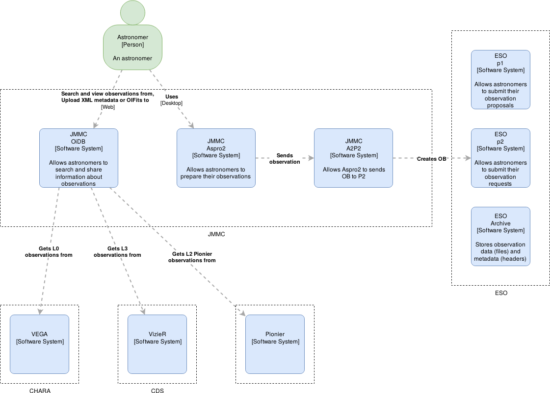
The architecture will be designed using the method described on https://c4model.comCurrent context around OiDB
 Source: JMMC-ObsPortal-C1-current.drawio
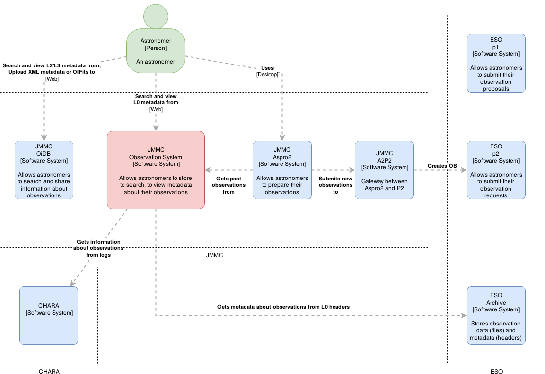
ObsPortal architecture
Level 1: System context
A System Context diagram provides a starting point, showing how the software system in scope fits into the world around it. Source: JMMC-ObsPortal-C1.drawio
Comments
At this step, a first question is related to the integration and the future role of OiDB and A2P2...Level 2: Container
A Container diagram zooms into the software system in scope, showing the high-level technical building blocks.Level 3: Component
A Component diagram zooms into an individual container, showing the components inside it.Level 4: Code
A code (e.g. UML class) diagram can be used to zoom into an individual component, showing how that component is implemented. --| I | Attachment | History | Action | Size | Date | Who | Comment |
|---|---|---|---|---|---|---|---|
| |
JMMC-ObsPortal-C1-current.drawio | r2 r1 | manage | 2.9 K | 2019-11-27 - 13:49 | PhilippeBollard | |
| |
JMMC-ObsPortal-C1-current.png | r2 r1 | manage | 83.1 K | 2019-11-27 - 13:50 | PhilippeBollard | |
| |
JMMC-ObsPortal-C1.drawio | r2 r1 | manage | 2.4 K | 2019-11-27 - 10:14 | PhilippeBollard | |
| |
JMMC-ObsPortal-C1.png | r2 r1 | manage | 81.2 K | 2019-11-27 - 10:24 | PhilippeBollard |
Topic revision: r4 - 2019-11-27 - PhilippeBollard
Ideas, requests, problems regarding TWiki? Send feedback


